Wings Overview
NOTE
Before we discuss wings in the PlaneMaker sense, we need to make a distinction between a wing and a wing panel. PlaneMaker allows you to create wing panels, one per tab, and you can combine multiple wing panels to form an Overall Wing. When we say wing or wings in this section, we mean a wing on one wing tab only, with one semi-length value. When we say overall wing then we mean a wing in the aircraft context which may or may not consist of multiple wing panels. A single wing panel can constitute an overall wing for simple wing planforms. We may use the terms wing and wing panel interchangeably depending on context.Standard Wings
Standard Wings are simply the term we give to the most common flying surfaces found on most aircraft. PlaneMaker groups these together under the Wings menu item for convenience. There are two types of standard wing panels: symmetrical and non-symmetrical. The image below shows which wing tabs are which type.
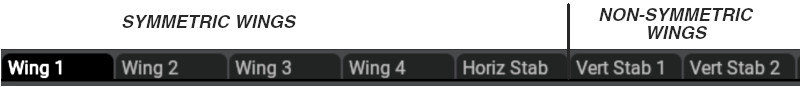
In X-Plane, all wings are the same type of entity and all have the exact same options and parameters to define their shapes; however, you will note that there are multiple tabs for the various wing panels such as the horizontal and vertical stabilizers. While the parameters to configure all wings and stabilizers are the same, horizontal and vertical stabilizers have special controls available to them on the Expert > Special Controls GUI and so are configured separately.
When configuring symmetrical wings, PlaneMaker will automatically create two wings, mirrored about the centerline. When you create a non-symmetrical wing, then PlaneMaker will create a single wing on the right side by default, but with a checkbox option to make it a left side wing. For a single vertical stabilizer on the centerline, it does not matter if the wing is set to be left or right, but for a twin-tail configuration, then clearly one vert stab needs to be a left, and the other a right.
Miscellaneous Wings
In addition to the Standard Wings shown above, PlaneMaker allows for up to 36 additional Miscellaneous Wings, 18 under the Standard > Misc Wings 1 menu item and another 18 under the Standard > Misc Wings 2 menu item. All Miscellaneous Wings are non-symmetric, but have the exact same configuration parameters as any other wing. You may note that the Vertical Stabs in the Standard Wing window are essentially miscellaneous wings, but only put in the Wings menu for convenience. An example use of a misc wing would be for a tri-tail configuration such as is found on the Lockheed Constellation, where the outer Vertical stabilizers would be configured in the Standard Wings window and a Miscellaneous Wing would be used for its central vertical stab.
Planform
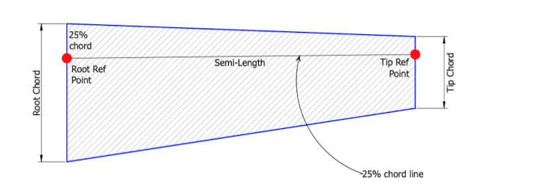
Wing planforms are defined by either 2 or 3 parameters. For a wing to exist in PlaneMaker, the semi-length and at least one of the chords (root or tip) needs to be set > 0. Until the wing has at least two valid plan parameters, the wing will not exist and therefore will not be visible in the preview panel. The semi-length is the length of the 25% chordline, that is a line that begins aft of the leading edge, located at 25% of the root chord length, and terminates at 25% of the tip chord length. The 25% chordline defaults along the X-axis unless a non-zero wing-sweep angle has been set. The wing position is determined by the Root Ref Point, which defaults to X, Y, Z = (0, 0, 0).
Airfoil Sections
Airfoil section profiles are neither specified nor configured via the Wing UI windows discussed in this section. Once you have the wing planform configured, you can then specify the section airfoils via PlaneMaker's Wing Airfoils Window. See the next section on Airfoils for more information about specifying airfoils.
Sweep and Elements
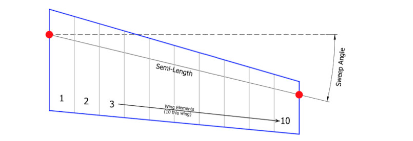
Wings may consist of anywhere from 1-10 elements. One element per 10% of the overall semi-SPAN (not semi-length...see next section below) yields good results in X-Plane. The illustration below shows 1 wing with 10 elements with a non-zero, positive sweep angle applied. Negative sweep angles may be used for forward swept wings.
Multiple Wings
A single PlaneMaker wing panel typically represents a simple trapezoid shape with continuous, straight leading and trailing edges. More complex planforms with discontinuous breaks/bends in the leading and trailing edge lines may be created using a single wing panel by using custom chords as described further below; however, this is not a common practice due to the 10 element per wing panel limit mentioned above. Discontinuous wing planforms generally require more than 10 elements to model the wing effectively.
The preferred method to model discontinuous planforms is to use multiple wing panels. This is why the Wings window has four Main wings available. Four is usually enough for most main wing planforms. If you need more, then the Miscellaneous Wings may also be used.
NOTE
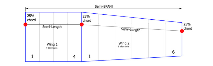
The semi-LENGTH is the length of the 25% chordline of ONE X-Plane wing panel only. The semi-SPAN is one-half of the overall wingspan of the aircraft, taking into account all wing panels.The illustration below shows two wing panels to model a planform similar to that found on a Cessna 172. Wing 1 has been set to four elements and no sweep and Wing 2 has been set to 6 elements with a slight sweep angle. Wing 2 has been located at the tip of Wing 1 and the tip chord length of Wing 1 = the root chord of Wing 2. The two semi-lengths of each wing contribute to the overall semi-span of the total wing. PlaneMaker provides a convenience button to quickly snap wings to the tip of other wings. If you have multiple wing panels and need to shift the overall wing around, this becomes a handy feature. See PlaneMaket snap to widget on the Wings Window, just below the Vert Stab 2 tab.
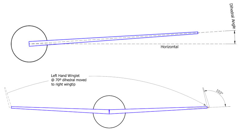
Dihedral
Dihedral is the angle of the wing from the horizontal, when viewed from the front or rear of the aircraft. A vertical stabilizer is simply a wing with 90º of dihedral, which is the maximum amount that may be set to a wing panel. If you need more than 90º of dihedral for any reason, then you can use a miscellaneous wing, which is non-symmetrical and move it to the opposite side from its sideness setting. So for example, a left-hand miscellaneous wing, set to 77º dihedral, but then relocated to the tip of the right wing, results in a right-wing winglet with 103º of dihedral.
Incidence Angles
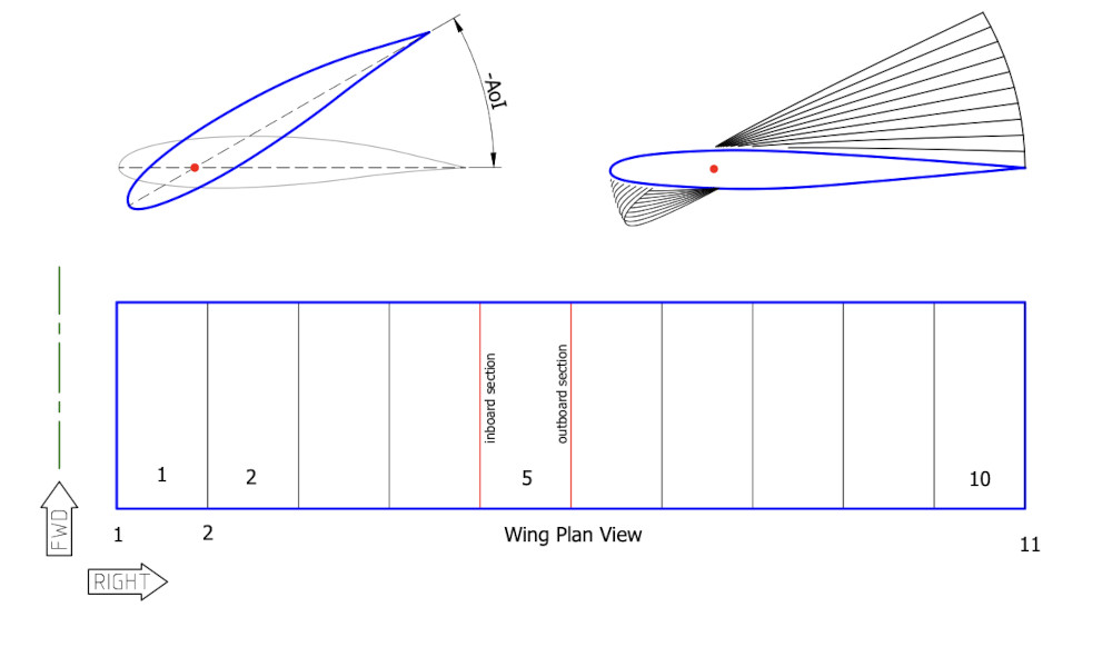
The angle of Incidence (AoI) is the angle of an airfoil section's chordline relative to some reference line, usually a horizontal one. The center of rotation of the foil sections in PlaneMaker are located approximately as shown by the red dot in the illustration below. In reality, the rotation point can be anywhere, but its usually near the aerodynamic center of the foil sections for construction and structural reasons.
The upper left example below shows an airfoil with an exaggerated negative AoI. The upper right example shows 11 sections (10 PlaneMaker elements), with each element incidence set to -3º more than the element before it, beginning with the root section (blue) at 0º.
In the bottom example, element 5 illustrates that there are 2 airfoil sections for each wing element, so for 10 elements in a wing panel, there are 11 sections. In PlaneMaker, you set AoI per element, which means if you have 10 elements, you have 10 incidence settings. This paradigm results in some notworthy effects when you set the AoI for the 1st and last elements in a wing panel.
NOTE
When you set the AoI for any element OTHER than the 1st or last elements (1 and 10 in the below example), then PlaneMaker will set both the inboard and outboard foil sections of the element to the same AoI value. The 1st and last elements; however, will only have their endmost foil sections set to the AoI entered in PlaneMaker, and their opposite element sections will be set to half of the AoI value entered. For wing panels <= 4 elements that have non-linear twist, this could result in section AoIs that may not represent your design intent.
Swing / Swept Wings
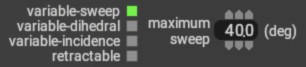
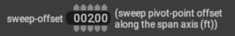
Specify a wing to be a swept wing, such as found on the F-14 / F-111, at Expert > Airfoils > Wings Tab as shown below. Enable the variable-sweep checkbox and specify how far the wing can sweep. Swept wings will rotate about their Root Chord Reference Point by default; however, you can alter the hinge/pivot point location by entering an offset value on the relevant Wings Tab (Standard > Wings page). Positive values move the hinge point inboard, negative values are not allowed.
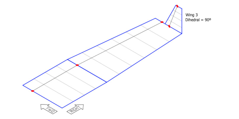
Winglets
Winglets are simply wing panels, defined like any other wing, and located outboard of the outermost wing panel and given some amount of dihedral. The illustration below shows 3 Main Wing panels where Main Wing 3 has 90º of dihedral. This wing panel was snapped to Main Wing 2 and then manually moved aft along the long arm a bit so the trailing edge aligns with Main Wing 2. The next section discusses how to move wings around.
Wing Placement
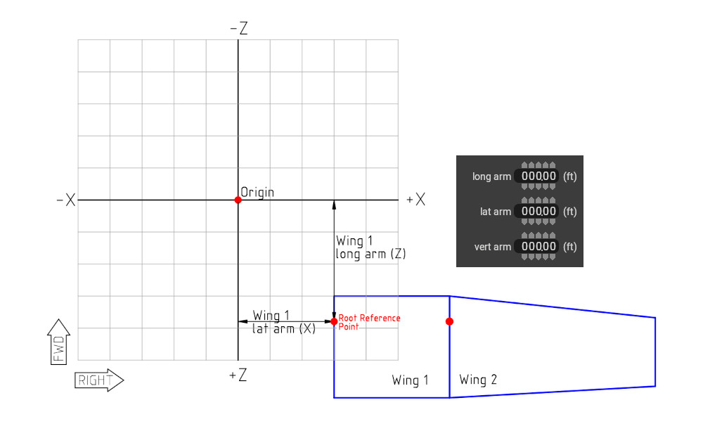
Wing panels are located according to the (X,Y,Z) position of their Root Reference Point. In PlaneMaker, theses X, Y, and Z coordinates are labeled as the long arm, lat arm and vert arm respectively where:
- X = lat(eral) arm
- Y = vert(ical) arm
- Z = long(itudinal) arm
It is common to use multiple wings adjacent to each other and PlaneMaker has a snap to function to allow you to place the Root Reference Point of one wing to the Tip Reference Point of another wing.
Custom Chords
Previously, we said that a wing panel can only represent a simple trapezoidal shape, which is not true. You can create more complex planforms using a single wing panel; however, its a bit more work and most do not use it. You do so be enabling the customize chords checkbox.
Wing Controls
See the Page on Control Surfaces