Airfoils
NOTE
Note that we do not discuss airfoil theory or the theory of lift in this section, but rather only how X-Plane models them and how to implement them in PlaneMaker for your lifting surfaces. This section assumes you have some basic knowledge of Airfoil behaviors. Our explanations here will be basic, simple, and suitable for working with Plane Maker and Airfoil Maker.
If you want to research more on the Theory and Aerodynamics of Airfoil Sections, then you can check out the following chapter from Embry Riddle's free online ebook on Aerospace Flight Vehicles:
AERODYNAMICS OF AIRFOIL SECTIONS
Airfoils Overview
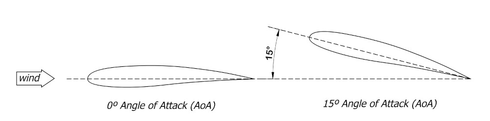
Airfoils come in all sorts of section profiles. When air moves over an airfoil, they produce three characteristic forces: Lift / Drag / Moments, which are imparted to the overall aircraft. The magnitude of these forces are dependent upon several factors common to all airfoil profiles, such as airspeed, air density, wing size, angle of attack etc; however, the shape of the airfoil section is the most dominant factor in establishing the total force when all the other variables are the same.
Click to Enlarge
Airfoil behavior for each of these three force types is characterized and contained in what are called Coefficients. These coefficients change as a function of Angle of Attack, that is the angle between the chordline of the airfoil and the direction of relative wind flowing over it. Each airfoil profile have its own characteristic Coefficients over a range of AoA. Historically, an airfoil's characteristic coefficients are determined through experimental testing; however, nowadays there are softwares to allow you to calculate the coefficients to a reasonable degree, though testing is the ultimate method. The three coefficients are:
- Lift Coefficient (Cl)
- Drag Coefficient (Cd)
- Moment Coefficient (Cm)
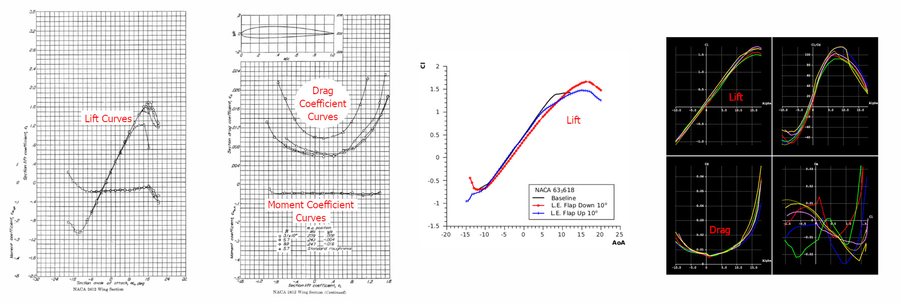
When these coefficients are plotted as a function of AoA, they result in 2-dimensional curves and its these curves that are used when designing aircraft wings and analyzing their performance. These curves are called simply, the Lift Curve, Drag Curve (or Drag Polar), and Moment Curve respectively. The coefficients themselves are identified symbolically via the terms (Cl, Cd, Cm). Note that the 2nd letter in these variables are lower case. This is typical when referring to the coefficients of the 2D airfoil. When referring to the overall coefficients of an entire 3D wing, possibly consisting of many airfoil sections with differing coefficients, then an upper case 2nd letter is used, i.e. CL, CD, and CM respectively.
The image below shows some representative curves for 2D airfoil sections, established through both experimental (wind-tunnel) methods as well as computer methods. Multiple curve types are sometimes plotted on the same plot for easy comparisons. You may note that there are multiple overlaid plots for a given curve type. This is due to the variation of coefficients with respect to airspeed, or more specifically, the Reynolds Number, so it is typical to have a range of curve types over a range of Reynolds Numbers. Curves for each coefficient type have characteristic shapes, such that you may know the coefficient curves you're looking at simply from the general shape.
Click to Enlarge
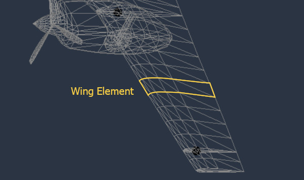
These Airfoil curves are at the very heart of X-Plane's Blade Element model. X-Plane simulates and keeps track of the air moving over each element that comprises a wing, so by simply knowing what the Cl, Cd and Cm is for each element, X-Plane can calculate the forces on that element, and further, by adding up the forces on all the elements, X-Plane can calculate the total forces on the overall wing, and thus on the entire aircraft. Plane Maker allows you to assign multiple airfoil sections to Wings.
Airfoil Maker
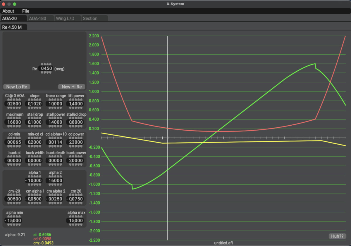
The very essence of Laminar's Airfoil Maker software is to configure/build these coefficient curves over a range of Reynold's numbers, and save that data as airfoil files, that can then be assigned to wings and props. In the screenshot below, notice the resemblance between the experimentally obtained curves above and the parametric curves shown in PlaneMaker. Green = Cl, Red = Cd, Yellow = Cm.
Click to Enlarge
Airfoil Maker uses configurable parametric curves to shape specific regions of each type of curve, the goal being to tweak the overall curve shape to mimic the curves of the airfoil you want to model. By adjusting the various parameters, you can manipulate the total curve shapes. The end-result is a Laminar proprietary format Airfoil file with the file extension .afl. Laminar have several default .afl files available to all aircraft, but you can create your own, or modify existing ones.
These files are human readable text files. It is possible to generate the data for the airfoil file with software other than Airfoil Maker; however, this is an advanced method requiring specialized knowledge and manual data merging techniques. Airfoil Maker is more than sufficient to create very accurate airfoil behaviors.
[TODO] Segue into Airfoil Maker and also the PlaneMaker stuff.