Vaccuum Systems
Overview
Vacuum systems are used to power gyroscopic instruments without requiring electricity. Vacuum systems are typically found on piston singles, twins, and vintage aircraft. X-Plane simulates two vacuum circuits, one for the pilot side and another for the copilot side. Which circuit any particular vacuum instrument is on depends on which datarefs or panel instruments you utilize. Datarefs and legacy 2D instruments for vacuum driven instruments are provided for both pilot and copilot sides and the sideness is reflected in the dataref and instrument names.
Vacuum Sources
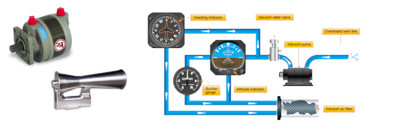
There are 3 sources of vacuum available in X-Plane:
- Engine driven vacuum pumps
- Venturi Tube
- Backup electrical vacuum pump
Two vacuum circuits (pilot/copilot) are always available when at least one engine is specified, whether you use vacuum instruments or not. Again, you use the circuits whenever you utilize the vacuum related datarefs/instruments. For a single engine configuration, both circuit's suction is derived from the one engine RPM. For a multi-engine aircraft, the pilot circuit suction is derived from engine #1 (index [0]) RPM and the copilot circuit derived from engine #2 (index[1]) RPM.
NOTE
X-Plane does not simulate vacuum pumps "per engine", but only uses the first two engines attached to the aircraft as described above. If you want to design a four engine piston aircraft with vacuum pumps on the right side only (engines 3/4), you're out of luck with default X-Plane. The good news is this model can simulate all known vacuum configurations we are aware of. You just do not see engine driven pump designs on aircraft bigger than a small piston twin.
A Venturi Tube vacuum source may be simulated by enabling a checkbox in PlaneMaker Standard > Systems > General 1 Tab > Instruments Panel. When enabled, then suction is available to all instruments regardless of sideness, and will invalidate/override X-Plane's engine/electric vacuum pump model.
An electrical standby vacuum pump is also available and connected to the pilot side circuit only. See Cross-Tied Circuits below for additional info.
Source Actuation
Engine driven vacuum pumps do not have to be actuated, they simply provide suction if they are not failed and the engine is running. (See Modeling Failures for more info on failed components)
The Venturi Tube source does not have to be actuated either. X-Plane assumes a venturi exists in the propeller slipstream of engine #1 (index[0]) and so will provide suction whenever engine #1 is running, and of course with sufficient airspeed. X-Plane's aerodynamics model establishes the air velocity flowing through the venturi and subsequently how much suction will be available based on that air velocity.
The electrical standby vacuum pump depends on electrical bus 1 for power, and will create vacuum according to the bus voltage. There is currently no bus assignment, nor bus load amperage setting for the electric vacuum pump. This pump is actuated via a switch, represented by the following dataref, where 0=OFF and 1=ON.
sim/cockpit2/switches/standby_vacuum_pump
Suction Indication
Each circuit's suction is represented via the following indicator datarefs.
sim/cockpit2/gauges/indicators/suction_1_ratio
sim/cockpit2/gauges/indicators/suction_2_ratio
The max instrument suction available to the above datarefs is an arbitrary value set in Standard > Systems > Limits 2 and the default value is 8. The max value is 99.9. This allows you to scale the suction ratio values into whatever units you need.
When the suction gets to be low on either circuit, then the following annunciator dataref will indicate so.
sim/cockpit2/annunciators/low_vacuum
If you need to track which system is low, then you can compare the suction ratio dataref values to see which is lower.
Cross-tied Circuits
Each of the two vacuum circuits may be cross_tied by enabling a checkbox in Standard > Systems > General 1 Tab > Instruments Panel, effectively making one circuit. There is NO dataref for the vacuum cross-tie. In practice, any vacuum system with two sources of vacuum will always be cross-tied. There is no practical scenario for isolating the circuits as is done with electrical gyros to conserve power consumption or battery life with an alternator failure.
Enabling the cross-tie checkbox is appropriate for the following two scenarios:
- Single-engine driving two vacuum pumps for redundancy.
- Any twin-engine with vacuum pumps on each engine.
System Failures
Each side can be failed via the datarefs below. rel_vacuum is the pilot side and rel_vacuum2 is the copilot side. The value of these datarefs use Laminar's default failure_enum
sim/operation/failures/rel_vacuum
sim/operation/failures/rel_vacuum2
When a simulation utilizes a cross-tied configuration, then both circuits must be failed for any of the gyro instruments to fail. This models a redundant design.