Introduction to PlaneMaker
General
Welcome to PlaneMaker (PM). PM is a GUI based, preprocessing application that allows you to create a model of just about any type of aircraft configuration you can think of: Gliders, jets, twins, carnards, rockets, balloons, V-tails, twin-booms, and more. Once you have created and saved your model with PlaneMaker, you can then open it in X-Plane and let X-Plane’s renowned flight and systems modeling algorithms simulate your creation and show you how it performs.
This manual assumes you have knowledge and experience with X‑Plane and its User Interface. It also assumes you have a basic understanding of aircraft, aircraft systems and aerodynamic principles and terminology.
This manual is a suitable reference for the individual parameters and widgets found throughout PlaneMaker's User Interface, containing basic explanations about what each parameter does. This manual complements the tooltips and video links found within PlaneMaker, yet provides additional examples and expanded information, allowing for a more thorough understanding of X-Plane aircraft modeling methods. This manual is intended to be searched & browsed for reference to specific parameters within PlaneMaker and is NOT suitable as a tutorial for how to model an aircraft. Tutorials on how to create aircraft with PlaneMaker are available and discussed below <TODO: add links to any tutorials or remove this sentence)
PlaneMaker Interface
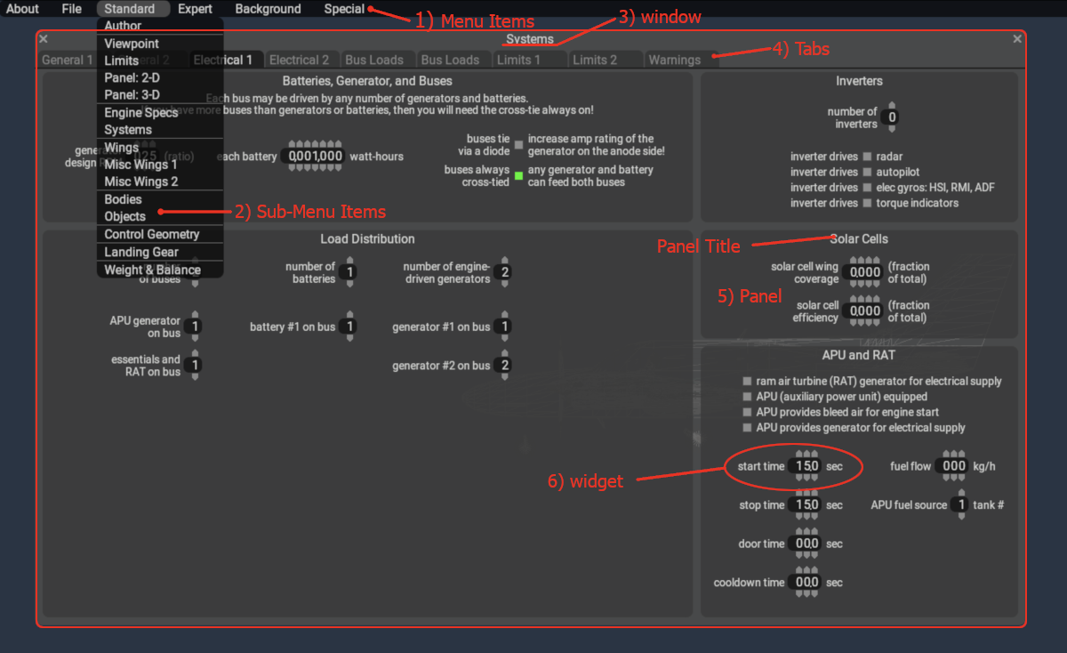
PlaneMaker's User Interface (UI) consists of numerous widgets (also called parameters) spread throughout the program. A widget may be a pulldown menu, a text box, a graph, a number box or checkbox, etc. These widgets are organized and grouped according to their functionalities, with related widgets typically appearing together. Widgets are located through a sequence of UI navigation elements and generally navigated to in the order shown below. The image at right shows the elements listed in the table at left.
| Nav Element | Description |
|---|---|
| 1) Menu Item | The top level menu item at the top of every PM page. |
| 2) Sub-Menu Item | The menu items listed underneath the top level Menu Items. |
| 3) Window | The displayed window (screen) in its entirety. Each Sub-Menu Item above has its own Window. |
| 4) Tab | Navigational tabs at the top of a window. Most windows have tabs, but not all. |
| 5) Panel | A rectangular sub-region within a Window. Panels usually have a Title |
| 6) Widget | Any field where you can enter data or enable options. |
NOTE
When we reference a Widget Location in PlaneMaker, we generally refer to the above sequence of Nav Elements in the same order as listed in the table above. In most cases, the Sub-Menu Item and Window Name are the same item so they are typically combined, so for the red circled widget in the image at right, its location would be notated:
Standard > Systems > Electrical 1 Tab > APU and RAT panel > start time widget
About These Documents
This PlaneMaker Manual takes a somewhat unique approach to presenting information for modeling aircraft in X-Plane. It is not organized into a sequential list of chapters as many other manuals are, but rather is organized into the following four resources for finding information quickly during development. You should become familiar with each to get the most out of this manual. After reading through this page, then the Navigation Panel at left should begin to make more sense. The four ares of this manual are:
- UI Reference Pages
- New ACF First Step Pages
- Modeling Concept Pages
- Search Box
WARNING
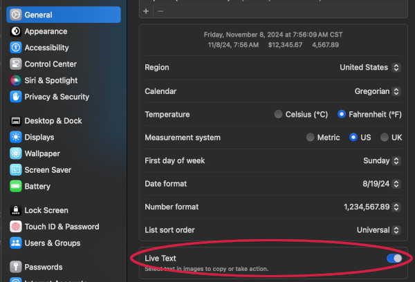
This manual makes heavy use of mouseover gestures on images to display popup tooltips. On Mac OSX, if you have Live text enabled in your Language settings (Montery / v12+), then this will interfere with the mouseover gestures and cause inconsistent tooltip popup behavior as the OSX Live Text feature attempts to select the text in the image.
UI Reference Pages
UI Reference Pages are provided for two purposes:
- When you know where a widget is in PlaneMaker, but want to know more about what it does.
- For general exploration of the PlaneMaker interface and widgets.

UI Reference Pages are characterized by showing the full PlaneMaker Window at the top of the page as shown at left. This is in contrast to the Modeling Concept Pages discussed below, where only the PlaneMaker Menu Bar is presented, but not the PM window. The UI Reference Menu Bar is available on nearly every Page of this manual; however, on those pages where it is not (such as this one), you can access the emulated PM interface by clicking on the PlaneMaker / Handbook text in the Top Bar.
On every UI Reference page, PlaneMaker's menu bar and window navigation tabs are emulated and you may navigate the emulated PM interface in the same way that you navigate in PlaneMaker itself. On any given page, you can hover the mouse cursor over the widgets to see pop-up tooltip explanations of the widgets. Not every widget has a pop-up tooltip, as some are self-explanatory, but most do. In some cases, clicking on the widget may take you to other areas of the manual for more information and in these cases, the pop-up tooltip will indicate so. Note that, due to the nature of how the pop-up tooltips are implemented, the content will not resize with the browser window. This manual is best viewed on full-size screens.
The area underneath the emulated PlaneMaker window is reserved for General Information pertaining to the PM page, including Austin's HUH videos, and/or any UI Widget Expansions. Whenever a UI widget's function requires (or benefits from) more explanation than can be provided in the pop-up tooltip, then that expanded information will be provided in this area and the pop-up tooltip will indicate so and link to the expanded information. As such, any UI widget expansion paragraphs under the PlaneMaker Window will not be in any particular order, save for a General paragraph, which will always be first and should be read first. UI Expansion paragraphs are intended to be read after the pop-up tooltip; however, they may certainly be browsed ad-hoc if you like. This UI Reference Page structure can be seen in the example at left.
New ACF First Steps
X-Plane requires ACF files to have a minimum amount of information in order to load the ACF file into X-Plane. If any of the required information is missing when saving the ACF file in PlaneMaker, then PlaneMaker will present error messages alerting you to what is missing. For new Aircraft authors, this can be annoying, not knowing exactly what the minimum information is and getting message after message every time you try and save the file. For this reason, a short section on New ACF First Steps is provided at left.
Each of the links in this section will take you to the relevant UI Reference Pages whereupon the General Paragraph for that page will list any minimum required widgets to be configured. This is NOT a tutorial on making an aircraft, but simply a reference so you can quickly get your ACF file loading into X-Plane and move on to the fun stuff!
Aircraft Coordinate System (ACS)
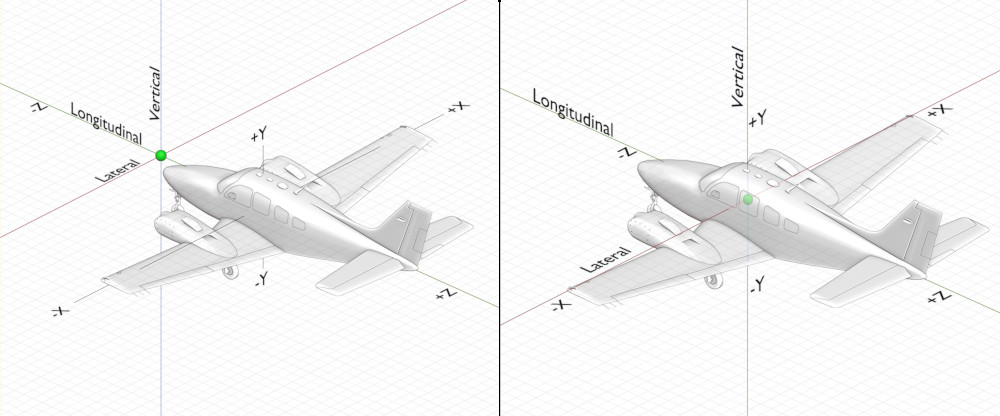
Many elements in PlaneMaker require you to specify a location in Cartesian coordinates. PlaneMaker uses the nomenclature, Longitudinal, Lateral, and Vertical to denote the Z, X and Y directions respectively. The global origin datum is an arbitrary point and you may place your geometry anywhere relative to the origin datum. Some authors will make the origin at, or some distance in front of, the nose of the aircraft, so that all longitudinal values (z) are positive. Others will align the empty Cg location of the aircraft at the origin datum, in which case points forward of the origin are negative and points aft arer positive. The image below shows the ACS with both origin options.
3D Viewport Options
- Still / Moving Controls
- Wireframe / Textures
- Day / Night Textures
Modeling Concept Pages

When most X-Plane aircraft authors model an aircraft, they generally think in terms of narrowly focused modeling concepts, and usually one at a time. For example, you don't think about your wing geometry model when your mind is currently concerned with your hydraulic model, nor do you think about landing gear configuration and electrical bus modeling at the same time.
Modeling Concept Pages are provided as a type of Notebook for various topics. These pages will typically contain more detailed instructions and explanations of X-Plane's various models and how they are configured using PlaneMaker. An example from the "Modeling Geometry > Wings" section is shown at right.
Modeling Concept Pages are organized into three broad categories, each represented by a folder icon in the navigation panel at left:
- Geometry (that affect aerodynamics)
- Powerplants
- Systems
The Modeling Geometry section contains Pages relevant to defining any geometric entities of your aircraft model. These are entities that change shape when their parameters are adjusted and have an affect on the aerodynamics of the model. The obvious elements are the wings and fuselage and control surfaces, but external weapons, airfoils and landing gear are also presented in this section.
The Modeling Powerplants section contains Pages relevant to defining any Powerplants used with your aircraft model. These pages are generally organized by Powerplant type, but includes a dedicated page for VTOL/Helos.
The Modeling Systems section contains Pages relevant to various sub-systems typically found in Aircraft. This section contains dedicated pages for Hydraulics, Electricals, Autopilots, Artificial Stability and many more.
Search Box
The search box is a valuable resource for quickly finding the information you need. The search box will search Headers and Sections of this manual, but not individual paragraphs. Section Headers have been created and labeled in such as way so as to be quickly located using the most probable search terms for any given aspect of PlaneMaker.
Changelogs
Changelogs for each version of PlaneMaker beginning with 12.1 can be found in the nav panel at left in the Change Logs folder. These logs will showcase changes to PlaneMaker and where those changes may be found.